
Heating intelligence · London homes
Smart Heating Controls for London Homes
Modern boiler modulation, weather compensation, radiators and underfloor heating working as one system.
Explore the complete guideModern boiler modulation, weather compensation, radiators and underfloor heating working as one system.
A comfortable home needs more than a good boiler and an attractive thermostat. It needs a heating system that understands which rooms require warmth, delivers it at an appropriate temperature and reduces its output as demand falls.
That becomes especially important when a London refurbishment combines underfloor heating downstairs, radiators on upper floors, several manifolds and a separate hot water cylinder. Each component may work perfectly on its own while the installation as a whole remains difficult to control.
The opportunity with a new installation is to plan those relationships before equipment is ordered. Rather than adapting a new thermostat to whatever happens to be in place, we can select the heat source, controls, distribution and room sensors together.
This guide focuses on current-generation heating controls for new installations and substantial refurbishments, including Vaillant eBUS and sensoCOMFORT, Viessmann One Base and compatible controls, and the integration of room-by-room systems. Existing-system conversions are covered separately because retaining equipment can limit what is achievable.
The aim is straightforward: comfortable rooms, sensible operating temperatures, dependable hot water and controls that the household can actually use.
The essential principle
A smart thermostat is one part of the system. Rooms, water circulation and the heat source must work together.
Start with the home before choosing the thermostat
A thermostat cannot decide how much heat a room needs at the coldest design conditions. That starts with heat-loss calculations, the building fabric and the output available from the radiators or floor.

We recommend establishing the intended use of each space before choosing a control platform. A home office occupied throughout the day has different requirements from a guest bedroom. A glazed kitchen extension responds differently from a sheltered middle-floor room. A bathroom may need warmth at times when the rest of the house does not.
The design brief should establish:
- Room heat losses and preferred comfort temperatures.
- Radiator and UFH outputs at the proposed water temperatures.
- Floor construction, coverings and permissible temperature limits.
- Which rooms need independent schedules.
- Domestic hot water demand and cylinder arrangements.
- Space for manifolds, pumps, controls and future maintenance.
- Whether heating must integrate with wider home automation.
These decisions determine what the controls need to do. They also prevent an expensive mistake: buying the visible devices first and discovering later that the concealed installation cannot deliver their promised functions.
For a wider refurbishment, heating controls belong within the complete heating and plant-room design, not as a final accessory added after the pipework is finished.
See our completed heating and plant-room installations for examples of coordinated installation work.
Understand the difference between rooms and heating circuits
Several terms are often used interchangeably, although they describe different parts of the system.
| Term | What it means |
|---|---|
| Room or comfort zone | An area with an agreed temperature and operating schedule |
| UFH loop | A length of heating pipe serving part or all of an area |
| Manifold | A distribution assembly supplying several loops or branches |
| Heating circuit | A water distribution circuit that may have its own pump and temperature control |
| Mixing circuit | A circuit in which a valve blends water to achieve a required supply temperature |
| Heat-source controller | The controller coordinating the boiler or heat pump and its supported system functions |
One large room may contain several UFH loops controlled together. One manifold may serve several independently controlled rooms. Two manifolds may share the same supply temperature.
Consequently, a house with three manifolds does not automatically need three thermostats, three mixing valves or three boilers.
For room control, trace the complete relationship: the sensor measures the space, the controller decides whether it needs heat, the appropriate valve or actuator responds, and the system provides the required circulation and heat input. Giving a room a name in an app does not create that relationship by itself.
For practical symptoms such as a thermostat calling for heat while the floor remains cold, see our underfloor heating troubleshooting guide for the distinction between demand, circulation and useful room heat.
A conventional thermostatic radiator valve regulates flow through its radiator but does not itself send a heat request to the boiler. A smart radiator valve can only participate in source demand where its control system is configured to do so. Otherwise, a room may ask for warmth while the main heating remains off.
Boiler modulation and the limits of simple on and off control
Modulation means that a boiler can vary its heat output within its operating range instead of producing the same output whenever the burner runs.
Two separate decisions are involved: how hot the heating water should be, and how much burner output is required to achieve that temperature.
A basic on/off thermostat passes a heat request to the system. A modulating boiler may still adjust its burner internally while responding to that request. It is therefore incorrect to say that every boiler connected to an on/off thermostat always fires at maximum power.
More capable controls can also influence the requested heating-water temperature. Instead of repeatedly requesting heat against an unnecessarily high fixed target, they can help the appliance respond to changing conditions. The exact division of responsibility depends on the boiler and controller. Vaillant ecoTEC plus technical documentation
Minimum output matters as well as maximum output
For a new installation, the boiler's lowest usable heating output deserves attention alongside its maximum rating.
Consider an illustrative situation in which only one small room requires heat. If the active load is below what the boiler can continuously supply at minimum output, the burner may need to stop and restart. A sophisticated thermostat cannot remove that physical limit.
This is why boiler selection, zone sizes, water circulation and control settings need to be considered together. Repeated short burner runs may indicate a problem worth investigating, although some cycling is normal when demand is sufficiently low.
The objective is not to keep the burner running at any cost. It is to provide the required comfort without avoidable starts, excessive temperatures or unwanted heating elsewhere.
Weather compensation and load compensation
Weather compensation changes the required heating-water temperature in response to outdoor conditions. Load compensation responds to indoor conditions, including the difference between the measured room temperature and the requested temperature. Zoning decides where heat is needed.
These functions address different questions and can work together where the selected system supports them. Energy Saving Trust explanation of heating controls
Weather compensation and the heating curve
A heating curve describes the relationship between outdoor temperature and the water temperature required by a heating circuit.
During milder weather, the building normally needs less heat. In colder conditions, the circuit may need a higher water temperature to maintain comfort. The curve should reflect the property and its emitters rather than remain on an arbitrary default setting.
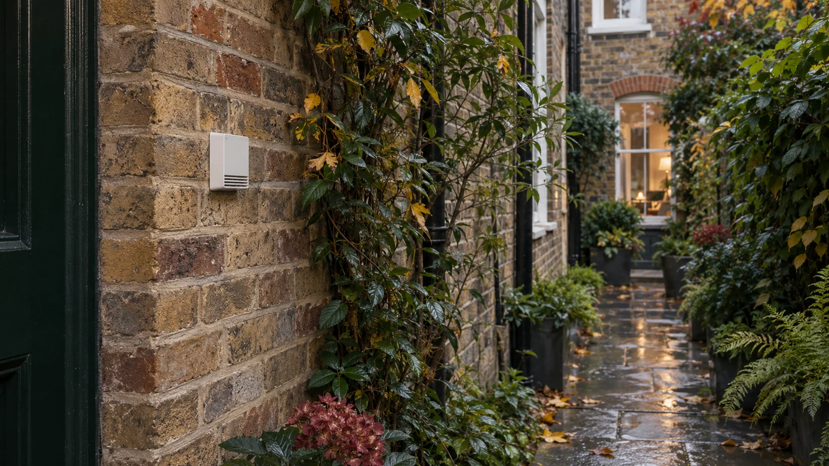
An outdoor sensor must also be positioned appropriately. A reading distorted by direct sunshine or another heat source can give the controller misleading information.
Some products use internet weather data instead of a dedicated outdoor sensor. The arrangements are not identical, so the source of weather information should be clear when comparing controls. Vaillant weather compensation guidance
Room influence and changing conditions indoors
Outdoor temperature does not describe everything happening inside a home. Sunshine through glazing, cooking, occupants and appliances can change the heat required in a particular room.
Suitable room feedback can help the control system account for those changes. However, a sensor in one sunny room should not inadvertently prevent a colder part of the house receiving heat. Sensor location, circuit assignment and room-influence settings matter.
Lower water temperatures can support efficient condensing operation, provided the emitters still deliver the required heat. The useful target is the lowest temperature that satisfies the relevant demand, not the lowest number available in a menu. Viessmann explanation of condensing-boiler temperatures
A floor can also be heating a room without feeling noticeably hot underfoot. Comfort should be assessed against room conditions and the design, not by expecting every surface to feel warm continuously.
What BUS communication adds to heating controls
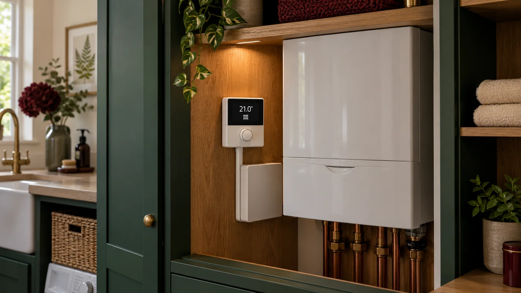
BUS describes a digital communication arrangement through which compatible devices exchange information. In heating, that may include temperature requests, operating states, sensor readings and faults.
It does not mean that every connected device takes direct control of the burner. Often the system controller determines a temperature requirement while the appliance manages combustion and its own protective functions.
Three distinctions are useful:
- OpenTherm is a manufacturer-independent communication protocol for compatible heating appliances and controllers.
- Vaillant eBUS is used within supported Vaillant control arrangements.
- Viessmann PlusBus connects specified controls and extensions on compatible Viessmann equipment. Other communications, including CAN on relevant platforms, have different roles.
These are not interchangeable simply because each uses digital communication.
OpenTherm can widen the choice of compatible controls, but additional functions depend on the particular products. A basic compatibility statement does not confirm every hot water, mixing-circuit or diagnostic function. OpenTherm Association
Similarly, Wi-Fi, Thread or a smart-home integration badge describes a different part of the connection. It does not establish compatibility with a boiler's control interface.
For a new system, we recommend selecting the required functions first and then choosing an approved combination capable of delivering them.
Vaillant eBUS and sensoCOMFORT in a new installation
For a current Vaillant installation requiring coordinated heating circuits and hot water control, sensoCOMFORT is an important option to assess.
It communicates through eBUS and supports weather-compensated system control. The current VRC 720/3 family, suitable room units and correctly selected expansion modules provide a route to managing more than a single thermostat request. Vaillant sensoCOMFORT
The components have different jobs. The system controller coordinates operation; sensors provide information; circuit modules provide the functions needed for the specified pumps, valves and circuits. A module such as VR 71 is not automatically a replacement for every room-actuator wiring centre.
The design needs to establish which circuits are direct or mixed, which room measurements influence them and how domestic hot water is controlled. Supported expansion depends on the selected arrangement, so a headline number of “zones” should not be treated as a room-by-room specification.
Combining Vaillant control with separate UFH room controls
A system can retain native Vaillant source control while using compatible third-party equipment for UFH rooms. Vaillant publishes system schematics illustrating such arrangements.
The important question is how the room demand reaches the system controller and how circulation and temperatures remain coordinated. This is a designed interface, not permission to combine arbitrary outputs from different products. Vaillant system schematics
For remote operation, myVAILLANT connect adds connectivity to supported systems. It does not replace the circuit hardware, and the scope of external smart-home integration needs separate checking. myVAILLANT connect
Viessmann One Base and integrated heating control
Current Viessmann installations should likewise be considered as a complete system rather than a boiler with a separately chosen thermostat.
The UK Vitodens range includes connected appliances such as the Vitodens 200-W, with native control and ViCare connectivity. The precise boiler type still matters: a product-family name is not a complete specification for the available circuits and accessories. Viessmann Vitodens 200-W
On compatible equipment, PlusBus supports specified controls and extensions. For example, Vitotrol 200-E is a wired remote control with a room sensor. Being able to operate several circuit programmes from a panel does not mean that the panel measures the temperature in every room. Viessmann Vitotrol 200-E
Where required and supported by the selected appliance, mixing-circuit extensions such as EM-M1 or EM-MX provide a different function from the room display or internet connection. They belong in the system specification alongside the pumps, mixer and sensors.
ViCare and room-by-room control
ViCare Smart Climate includes radiator controls, floor-heating controls and room sensors. In supported integrated arrangements, room information can contribute to the operation of the wider heating system rather than remaining isolated in a separate app. ViCare Smart Climate components
For a new installation, the practical questions are which functions the chosen UK appliance supports, which accessories are required and how room control interacts with the heating circuits.
We do not assume that built-in Wi-Fi confirms every possible control combination. Nor should a generic statement about OpenTherm replace a check against the exact appliance and controller.
With the system selected together from the outset, compatibility can be resolved before installation instead of becoming a problem at commissioning.
Radiators and underfloor heating can share a control strategy
A mixed system does not need to behave like two unrelated installations.
In a common arrangement, UFH serves the kitchen and ground-floor living areas while radiators heat bedrooms above. The two parts may have different schedules and response times, yet still use one coordinated heat source.
The design must answer three questions:
- Can each area request heat independently?
- Can satisfied areas stop receiving unwanted heat?
- Can each active circuit receive the temperature and flow it needs?
Radiators do not inherently require high-temperature water. Their required temperature depends on room heat loss and their output at the proposed conditions. Appropriately sized radiators may work within a lower-temperature design.
Equally, UFH is not one uniform type of emitter. Pipe spacing, floor construction, coverings and available floor area affect its output. Controls cannot compensate for an emitter that cannot meet the room's design load.
These choices should be resolved alongside the underfloor heating design, rather than assuming any radiator circuit can be added to any manifold arrangement.
Electric UFH is different: heating cables or mats do not receive water from the boiler or manifold. They require suitably rated electrical controls and the relevant floor-temperature protection. A shared app may offer a common interface, but it does not make electric and water-based heating interchangeable.
Thermostatic mixing and weather-compensated mixing circuits
Where the primary supply is hotter than the UFH circuit requires, mixing can reduce the temperature before water reaches the floor.
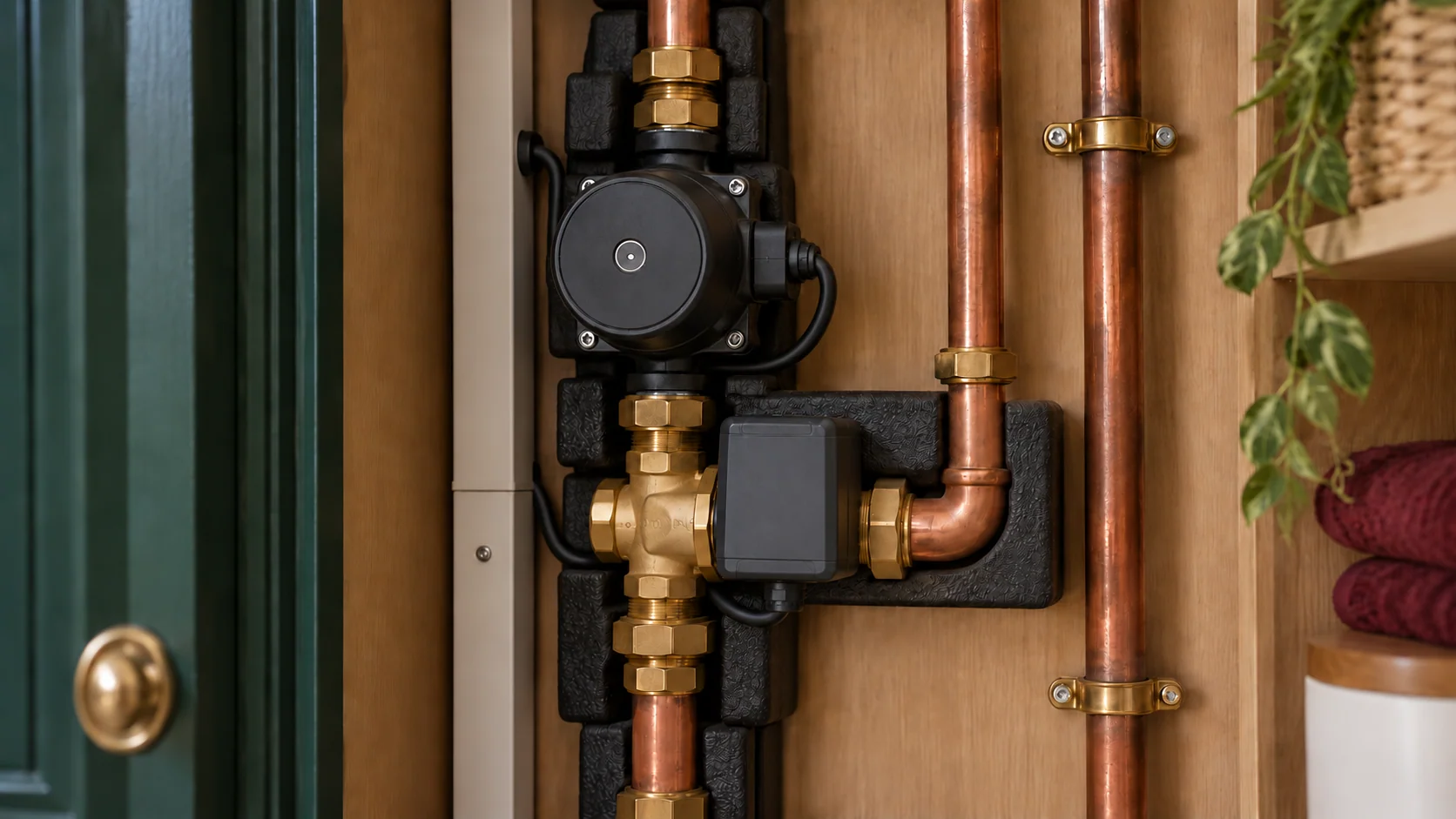
A thermostatic mixing valve normally regulates towards a preset mixed-water temperature within its operating conditions. It is a useful solution in an appropriate design, but it does not independently calculate a weather-dependent target.
A motorised mixing arrangement uses an actuator, temperature feedback and a controller to regulate the circuit. With suitable controls, its target can vary with outdoor conditions and the needs of that circuit. ESBE distinguishes these fixed-temperature and controlled-mixing arrangements in its technical material. ESBE circulation and mixing controls
This distinction matters when comparing quotes. “Weather-compensated boiler” and “independently weather-compensated UFH circuit” do not necessarily describe the same installation.
Our design recommendation is to specify the required behaviour explicitly. If radiators and UFH need different temperatures, establish how those demands are reconciled at the source and how the lower-temperature circuit is protected.
Conversely, mixing should not be added solely because a manifold exists. A compatible direct, low-temperature arrangement may be appropriate where the source, emitters, hydraulics and protective provisions have been designed together.
Air temperature, water temperature and floor-surface temperature remain different quantities. Relevant floor limits must still be respected.
When radiators supplement UFH in the same room
Combining two types of emitter in one room requires more thought than giving each its own unrelated thermostat.
A supplementary radiator may provide additional output where the available heated floor cannot meet the design heat loss. Alternatively, it may have a deliberately defined role in recovery or occasional use. Those are different design objectives.
The first task is to calculate what each emitter contributes. The next is to decide how they should cooperate.
Possible strategies include coordinated operation or a supported staged arrangement in which additional heat is requested under defined conditions. There is no universal rule that the radiator should always run first, always run second or use a fixed temperature offset.
One potential problem is that a fast radiator warms the room sensor quickly, ending the demand before the UFH has behaved as intended. Another is that the floor continues releasing stored heat after the radiator has already brought the room to temperature.
We recommend agreeing one coherent comfort strategy for the room, including sensor placement, emitter roles and recovery behaviour. The required logic must be available in the selected controls; not every multi-zone product provides the same functions.
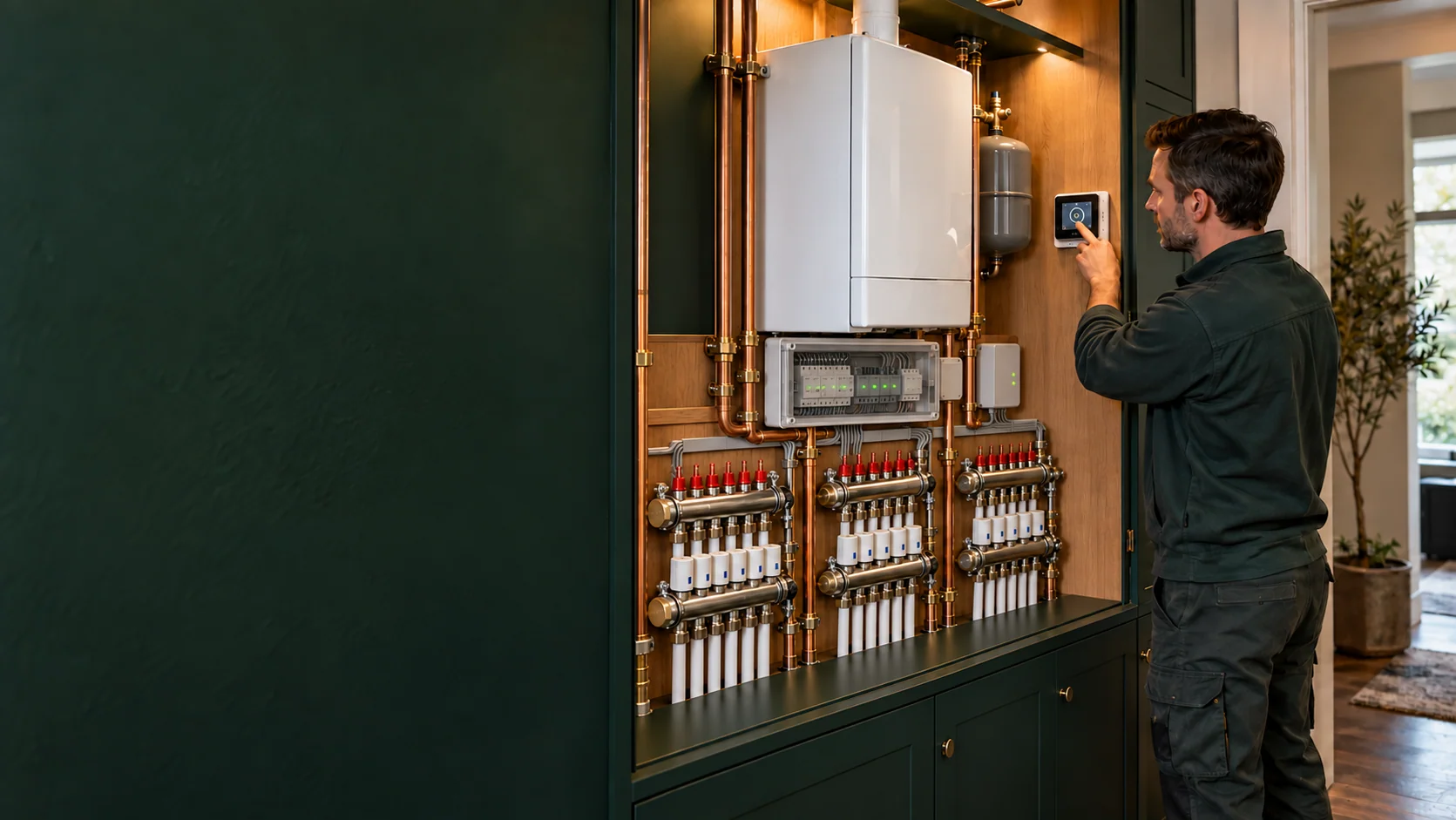
A three-manifold system explained
Consider an illustrative refurbishment with two UFH manifolds and a third manifold distributing water to radiators. This is a design example, not a claim about a completed PEP project.
The number of manifolds alone does not determine the controls.
Three distribution assemblies. One coordinated design.
Shared low-temperature operation
If the floor systems and radiators have been selected to work at compatible temperatures, the design may allow them to share a supply-temperature strategy.
Rooms can still have appropriate individual control. The remaining questions include flow distribution, pump duty, pressure losses and behaviour as zones close.
Different temperatures for different emitters
If the radiator circuit needs a different temperature from the floor circuits, the installation needs a suitable arrangement for producing and distributing those temperatures.
The two UFH manifolds might share a controlled mixing circuit or require separate circuits because their designs differ. The answer comes from their requirements, not their physical separation alone.
Supplementary radiators serving UFH rooms
If the third manifold supplies radiators in rooms already served by UFH, room-level coordination becomes essential.
The control schedule should identify which radiator and UFH outputs belong to the same space and how their combined operation is managed. Otherwise the plant room may be neatly labelled while the actual rooms remain difficult to regulate.
For all three cases, we recommend documenting a small set of operating scenarios before installation: one UFH room calling, radiators calling alone, simultaneous demand, hot water demand and the last heating zone closing.
If the intended response cannot be explained clearly, the control design is not yet complete.
Room controls from Wunda and Heatmiser
A room-control platform and the boiler manufacturer's system controller do not necessarily have to be the same product.
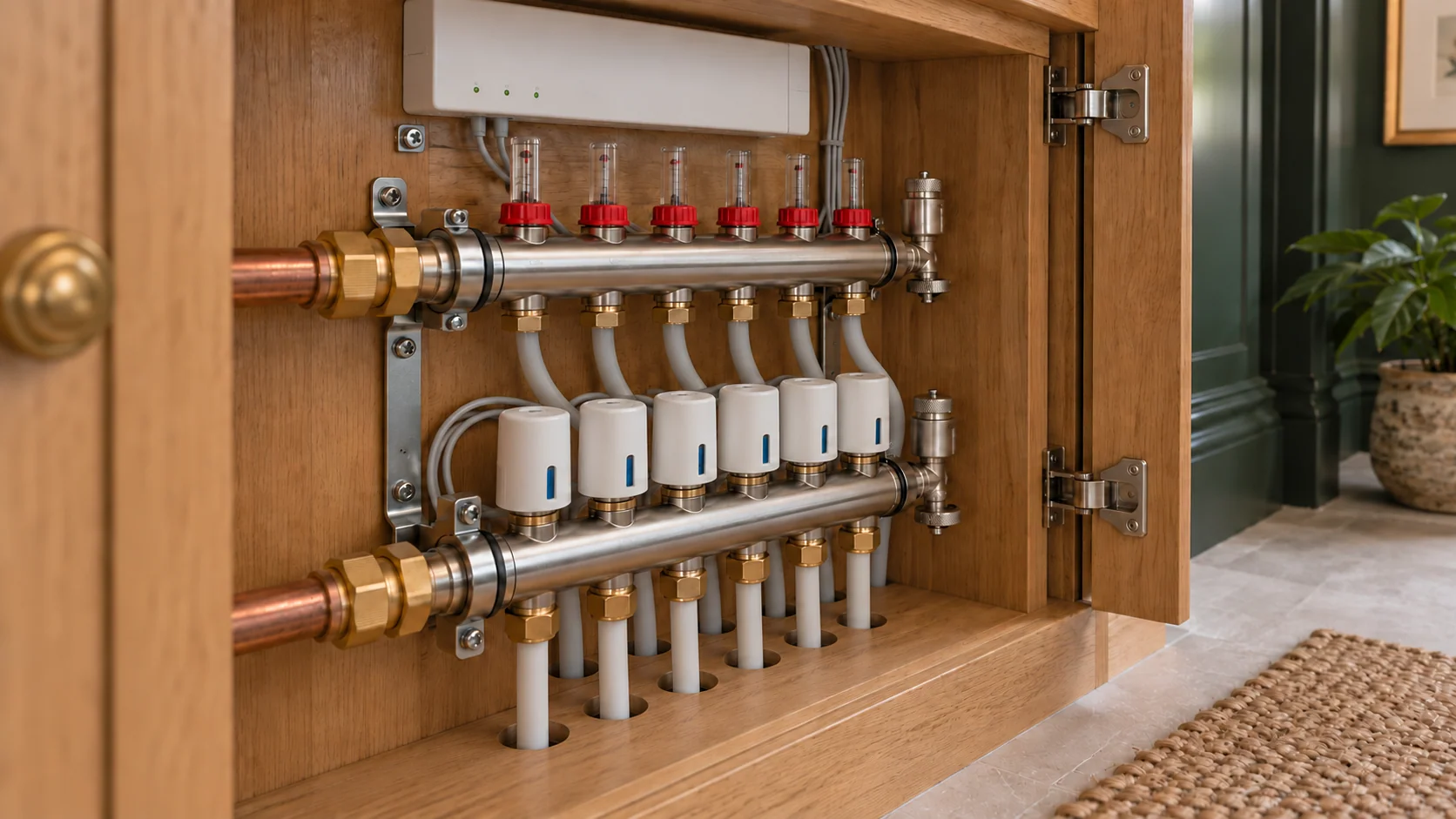
WundaSmart provides an ecosystem for room control across UFH, radiators and hot water using its supported devices. The HubSwitch, room sensors and distribution controls must be selected for their specific roles. WundaSmart controls
Current Heatmiser neo arrangements include wired options and wireless combinations such as neoAir v3 with UH8-RF v2. Their wiring centres provide defined functions for zone outputs and associated equipment; the configuration for a radiator zone is not necessarily identical to a UFH zone. Heatmiser neo system overview
Other platforms, including tado X, also document mixed radiator and water-based UFH arrangements. Their specified zone-control and hydraulic requirements still apply. tado X mixed-system guidance
Our recommendation is to assess these platforms against the required room behaviour, not choose a winner from the appearance of the app.
The specification should say whether the room controls pass a simple heat request or richer information, who determines the water temperature and how source operation ends. It should also distinguish a room valve from a manifold temperature-control device: they do different jobs.
Flow and minimum demand need their own design
Zoning changes the hydraulic conditions of an installation. When valves close, the active flow paths and available heat load change.
The design therefore needs to work with one small active zone as well as with the whole house calling. Pumps should operate within the intended conditions, and the heat source must retain the flow arrangements required by its manufacturer.
The answer is not automatically to add a buffer vessel or low-loss header. Hydraulic separation and additional water volume can solve particular problems, but they introduce their own design considerations and are not interchangeable remedies.
Similarly, leaving an arbitrary radiator permanently hot is not a substitute for establishing how the system should operate.
We recommend checking source minimum output, required circulation, pump control, hydraulic balance and the agreed zoning together. Where a bypass or other hydraulic provision is required, its purpose and settings should be part of the design.
The control arrangement must also prevent unnecessary heat generation when there is no demand. This is the purpose of boiler interlock, while allowing legitimate functions such as frost protection and pump overrun to operate as intended. Interlock does not mean disconnecting the appliance's power whenever the room is warm.
A digital link helps equipment exchange information. It cannot make water circulate through a closed path or increase the heat demand of a satisfied room.
Domestic hot water must remain a separate requirement
A hot water cylinder and a heating circuit have different jobs. The temperature suitable for maintaining a room through UFH may not be sufficient for the cylinder's required heating regime.
For the installation itself, our unvented cylinder and controls service coordinates the hot-water equipment, electrical connections and operating sequence.
Suitable system controls can distinguish space-heating operation from cylinder charging. Depending on the approved arrangement, hot water may take priority or operate alongside heating where the system is designed to support that.
Commissioning should establish what happens when the cylinder calls during a heating period and how the system returns to space heating afterwards. Higher-temperature cylinder charging must not expose the UFH circuit to unsuitable conditions.
Hot water settings must also preserve the required hygiene, scald protection and independent safety functions. An app schedule does not replace cylinder safety controls.
If the project includes a cylinder upgrade, our vented-to-unvented hot water guide explains the wider considerations.
A combi conversion creates a different arrangement by removing stored domestic hot water from the design. The heating controls should be reviewed as part of that change rather than simply reusing the old wiring assumptions. See our conventional-to-combi conversion guide.
Heating control within a wider smart home
Some projects need heating to interact with occupancy, shading, ventilation or a building-management system.
Here it is useful to distinguish monitoring from control. Displaying a boiler temperature in an app is different from setting its target, coordinating its circuits or managing its operating priorities.
Systems such as Loxone provide dedicated control functions, including mixing-valve regulation, but those functions still require the associated sensors, outputs and wider operating logic. Loxone mixing-valve control
For integrations using KNX, Modbus, BACnet or other supported interfaces, we recommend defining exactly which information and commands cross the boundary. An analogue 0–10 V input is another possible interface on suitably equipped plant, but it is not a digital BUS and its meaning must be established.
There should be a clear control hierarchy. Two independent systems should not repeatedly override each other's temperature targets or priorities.
Keeping native source protection and suitable manufacturer control while integrating agreed building-level functions can be a sensible approach. The correct solution depends on supported interfaces and a documented sequence of operation, not on making every device appear in one app.
Heat pumps and boiler cascades need different treatment
The same broad principles apply to heat pumps: suitable temperatures, coordinated demand and a properly designed distribution system. However, boiler habits should not be transferred without checking the heat pump's requirements.
Minimum flow and available system water volume can be particularly important, including during defrost for relevant air-source equipment. Manufacturers specify these for individual models. Closing many small zones must not undermine those requirements. Vaillant example of model-specific hydraulic requirements
Designing emitters for low-temperature operation can support a later heat-source change, but it does not guarantee that today's controls and accessories will suit every future appliance.
A boiler cascade is different again: it coordinates more than one boiler, including which units operate and how their output is managed. It is not a consequence of having several manifolds. Suitable manufacturer cascade controls and the wider plant design are needed.
We recommend treating cascade selection as a separate engineering decision for a property whose demand and resilience requirements justify it, rather than adding boilers simply because the control system is complex.
Wired and wireless controls and everyday reliability
A new refurbishment provides an opportunity to plan cable routes before finishes are completed. Wired controls can suit that approach, particularly where reliable connections and discreet sensor locations are priorities.
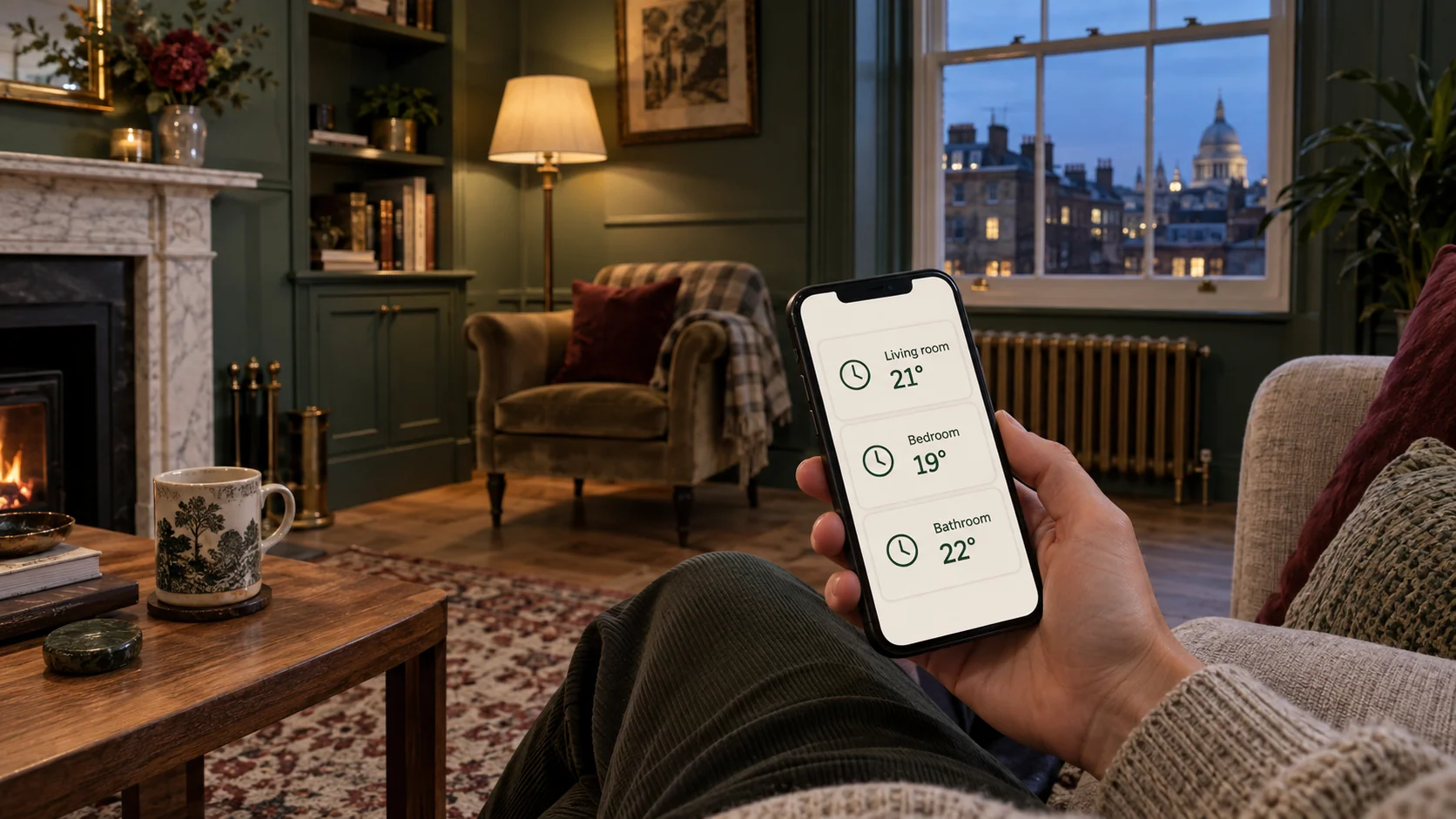
Wireless controls can reduce disruption and offer flexibility, but the final layout needs to be checked for coverage. Thick walls, metal enclosures and the position of the receiver can affect the practical result.
Neither option removes the need to consider maintenance and support.
When selecting a system, establish:
- Which schedules and settings remain available without internet access.
- What happens if the local router fails.
- How a lost room-sensor connection is reported.
- Whether batteries are needed and how low-battery warnings work.
- What happens after a power interruption.
- Which features require an account, subscription or ongoing cloud service.
These are separate questions. Loss of broadband is not the same as loss of the local network, and neither is the same as a power cut.
The owner should retain control of the main account. Any installer access should be agreed, and the handover should explain how to change users, manage permissions and obtain support.
Schedules should reflect the floor and the household
A high-mass screed floor can take longer to respond than a low-profile system with pipework close to the surface. Applying the same aggressive on/off schedule to both can produce disappointing results. Nu-Heat guidance on floor response and controls
For our recommended approach, the schedule should describe when the room needs to be comfortable, with recovery and setback chosen around the actual construction.
That does not mean every UFH installation should run at an unchanged temperature all day. Nor does it mean the largest possible overnight setback is always best. Occupancy, heat loss, response time and the source all matter.
Room sensors need representative positions, away from misleading local heat, draughts or concealment. Where floor sensing is required, its function and limits must also be configured correctly.
During initial use, note which rooms overshoot, recover slowly or remain comfortable. Those observations are more useful for adjustment than repeatedly turning the entire system up because one room behaves differently.
What changes when converting an existing system
A new installation gives us freedom to choose compatible components and design the control arrangement from the outset. It does not mean all makes and protocols can be mixed indiscriminately.
When converting an existing system, the retained boiler, valves, wiring, pumps or cylinder may limit the available functions. A newer thermostat may provide useful room scheduling without retaining every feature of a manufacturer's integrated controller. For floor construction, finished levels and the wider renovation scope, see our guide to planning a retrofit underfloor heating installation.
We recommend distinguishing three options: retain the existing source with a supported controls upgrade; replace selected distribution and control components; or design a complete replacement system.
The proposal should identify both the improvements and any functions that cannot be retained. Older generations do not need to dominate the discussion, but their limitations should be established before new equipment is ordered.
Flats connected to communal heating or a heat interface unit need a separate assessment. The dwelling's controls do not necessarily have authority over the building's central plant, and changes may require coordination with the building operator. A domestic boiler-control example should not be applied to that arrangement without checking the actual system.
Where the wider electrical installation also needs reviewing, our consumer unit replacement or full rewire guide explains how inspection findings, new loads and retained circuits help define the appropriate scope before finishes are closed.
Problems that controls alone will not solve
A cold room does not automatically need a more expensive thermostat. The fault may be a closed or sticking valve, air, restricted flow, poor balancing or insufficient emitter output.
| Symptom | What should be investigated |
|---|---|
| Radiators heat when only UFH is requested | Valve operation, demand mapping and unintended flow paths |
| A thermostat calls but its room remains cold | Correct actuator assignment, circulation, air and emitter capacity |
| Rooms overshoot their set temperature | Sensor location, recovery settings and emitter response |
| The boiler starts frequently with little demand | Minimum output, active load, temperatures and hydraulic conditions |
| Different rooms never behave independently | Zoning arrangement, valves and control configuration |
These are starting points for diagnosis, not remote fault determinations.
Likewise, sludge is only one possible reason for poor performance. Cleaning should follow evidence of contamination and a suitable assessment, not be sold as the automatic answer to every controls problem. Our guide explains when a heating system may need powerflushing.
What affects the cost of heating controls
The price of a thermostat is only one part of the cost.
A straightforward controls replacement is a different project from introducing independent radiator rooms, adding motorised mixing circuits or coordinating several manifolds with hot water and home automation.
A meaningful quotation should identify the control platform, sensors, actuators, circuit modules, pumps or valves being added, and any necessary hydraulic alterations. It should also address cabling, access, making good, programming, testing and handover.
In London refurbishments, finished surfaces, restricted routes and work in occupied properties can significantly affect the practical scope.
We recommend comparing complete outcomes rather than device counts. Two proposals may contain similar-looking wall controls while providing very different source integration, commissioning and support.
Running-cost savings should also be treated honestly. They depend on the existing installation, behaviour, building and achieved settings. There is no defensible universal saving percentage for every home.
Commissioning proves whether the design works
Successful commissioning involves more than confirming that every thermostat lights up and appears in the app.
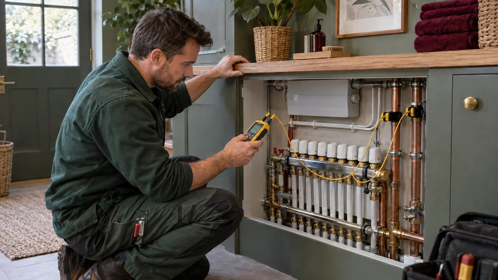
For a multi-circuit installation, we recommend an agreed test schedule that follows the intended operation of the system.
First, identify the equipment and map each room sensor to its actual valve, loop group or radiator branch. Names on the screen should match the room labels and physical installation.
Then test individual room demands and combinations of demands. The right circuits should respond without unintentionally heating unrelated areas. Flow and temperature behaviour should remain suitable when only a small part of the house is active.
Where a cylinder is installed, verify its demand, priority and return to space heating. Check the behaviour after the final heating demand ends, including required pump overrun and protective operation.
The review should also cover heating curves, temperature limits, room influence, valve travel and relevant operating delays. Internet loss, communication faults and restoration of power should be considered in accordance with the selected equipment.
The handover should include:
- A clear room and circuit schedule.
- Equipment details and useful manuals.
- Recorded operating settings and control responsibilities.
- Relevant commissioning and certification records.
- Owner access and agreed installer permissions.
- Guidance on schedules, overrides, holidays and faults.
Some fine-tuning may require observations in colder weather. Any follow-up review should be agreed as part of the project scope.
Regulations and safe installation
This guide concerns homes in England. Applicable requirements depend on the work, the building and the relevant transitional arrangements.
Heating efficiency and controls fall within the scope of Part L guidance. Electrical work must meet the applicable safety requirements, including the relevant inspection, testing and notification arrangements. Gas work must be undertaken by appropriately qualified Gas Safe registered engineers. Gas-work registration requirements, Approved Document L, Approved Document P.
At the October 2026 review of this guide, the published 2026 changes have a general commencement date of 24 March 2027, with specified higher-risk building provisions following on 24 September 2027, subject to transitional arrangements. They should not be described as already applying to every controls upgrade. New-build projects also require their own assessment of the applicable heating standards. Government commencement guidance
This is a planning guide, not wiring instructions. Safety interlocks, cylinder protection and appliance limits must not be bypassed to make an incompatible control appear to work.
Frequently asked questions
Can one system control radiators and underfloor heating
Yes, provided its room controls, distribution and source interface support the intended arrangement. “One system” can include more than one type of controller, with clearly defined responsibilities.
Does every manifold need a separate thermostat
No. A manifold distributes water; thermostats regulate spaces. One manifold may serve several rooms, and a large room may contain several loops controlled together.
Is BUS control better than an on and off thermostat
A supported digital connection can provide richer communication and temperature control. Its value depends on the complete installation. It does not automatically correct poor sizing, inadequate flow or unsuitable emitters.
Are eBUS and OpenTherm the same
No. They are different communication arrangements. A product supporting one should not be assumed to support the other.
Can Vaillant or Viessmann controls work with another UFH brand
Suitable combinations can be designed, but compatibility needs to cover demand signals, circuit temperatures, pumps, valves and hot water where relevant. The brand printed on the floor pipe does not determine the boiler-control interface.
Do smart radiator valves replace the need for balancing
Do not assume they do. The distribution still needs the required flows. Any manufacturer's automatic-balancing function must be assessed within its specified system conditions rather than treated as a universal substitute for commissioning.
Does a large house automatically need a buffer or several boilers
No. Those decisions follow calculations, source requirements and the hydraulic design. Floor area or manifold count alone is not enough.
Will the heating work without internet access
That depends on the selected equipment and the type of connection failure. Establish local operation, remote access and fallback behaviour before purchase, then explain them at handover.
Can the controls be upgraded without replacing the boiler
Often, but the retained appliance may limit integration. The proposal should distinguish improved comfort or scheduling from functions that require a different source or control arrangement.
Plan a coordinated heating system with PEP
For a new installation, the strongest opportunity is to make the important decisions together: heat source, radiator and UFH outputs, circuits, controls, hot water and the way the household lives.
PEP coordinates heating and electrical work for London residential projects. Our heating services and electrical installation work allow those interfaces to be considered within the wider refurbishment.
In SW6, our Fulham electrical installation service can coordinate control wiring and supplies with the heating installation. We also provide electrical installation and heating-control wiring in Hammersmith W6. For W12 projects, see our electrical installation and controls in Shepherd’s Bush. For SW5 installations, explore electrical services and controls in Earl’s Court. In NW6, our Queen’s Park electrical service coordinates supplies and heating-control wiring. For W2 projects, see Paddington electrical installation and controls.
If you are planning UFH with radiators, several manifolds or a new Vaillant or Viessmann installation, send us the property postcode, available drawings and an outline of the rooms and hot water requirements.
For an existing-system upgrade, externally accessible equipment labels and photographs can help the initial discussion. There is no need to open electrical enclosures or remove boiler covers.
Discuss your heating controls and installation with PEP.
The objective is not to install the greatest number of smart devices. It is to deliver a heating system whose rooms, distribution and heat source work together.